


 Direct purchase from the factory


![[US Direct] FlashFish P60 560W Portable Power Station 520Wh 140400mAh Solar Generator 110V Pure Sine Wave Power Generator For Camping Travel](https://static.roymall.com/d/file/mall/titlepic/232/krvcvjgyo4u.jpg?x-oss-process=image/resize,w_150/quality,Q_80/format,webp)


1.You can contact the customer service. for any question regarding the product.
2.Ask the question in English to get answer faster.
3.Keep your question short and to the point.
Questions:0/2000
 USD $ | United States
 USD $ | United States
 GBP £ | United Kingdom
 HKD HK$ | Hong Kong
 CNY ¥ | China
 JPY ¥ | Japan
 EUR € | Euro
EUR € | Germany
EUR € | Italy
EUR € | Spain
EUR € | Euro
EUR € | Germany
EUR € | Italy
EUR € | Spain
 SBD SI$ | Solomon Islands
 PGK K | Papua New Guinea
 THB ฿ | Thailand
 ILS ₪ | Israel
 VND ₫ | Vietnam
 MGA Ar | Madagascar
 XAG | Silver
 IDR Rp | Indonesia
 HTG G | Haiti
 PHP ₱ | Philippines
 MXN $ | Mexico
 WST WS$ | Samoa
 CAD $ | Canada
 LSL L | Lesotho
 BWP P | Botswana
 KRW ₩ | South Korea
 KWD د.ك | Kuwait
 LAK ₭ | Laos
 LKR Rs | Sri Lanka
 TRY ₺ | Turkey
 PKR Rs | Pakistan
 CHF Fr | Switzerland
 PLN zł | Poland
 QAR ر.ق | Qatar
 NAD N$ | Namibia
 MOP MOP$ | Macau
 EGP ج.م | Egypt
 MWK MK | Malawi
 VES Bs.S | Venezuela
 ECS S/ | Ecuador
 OMR ر.ع. | Oman
 XDR | IMF
 LTL Lt | Lithuania
 TJS SM | Tajikistan
 BBD Bds$ | Barbados
 BRL R$ | Brazil
 BZD BZ$ | Belize
 CRC ₡ | Costa Rica
 IRR ﷼ | Iran
 AED د.إ | United Arab Emirates
 PAB B/ | Panama
 VUV VT | Vanuatu
 DOP RD$ | Dominican Republic
 XOF CFA | West Africa
 AWG ƒ | Aruba
 YER ﷼ | Yemen
 XCD EC$ | East Caribbean
 GHS GH₵ | Ghana
 BDT ৳ | Bangladesh
 SRD $ | Suriname
 GMD D | Gambia
 MVR Rf | Maldives
 SVC $ | El Salvador
 BND B$ | Brunei
 GIP £ | Gibraltar
 SHP £ | Saint Helena
 GTQ Q | Guatemala
 AFN ؋ | Afghanistan
 IQD ع.د | Iraq
 AZN ₼ | Azerbaijan
 JOD د.ا | Jordan
 CLP $ | Chile
 BHD .د.ب | Bahrain
 NIO C$ | Nicaragua
 NGN ₦ | Nigeria
 UZS so'm | Uzbekistan
 ERN Nfk | Eritrea
 ANG ƒ | Netherlands
 KYD CI$ | Cayman Islands
 SYP £S | Syria
 SDG ج.س. | Sudan
 LBP ل.ل | Lebanon
 HNL L | Honduras
 DJF Fdj | Djibouti
 TTD TT$ | Trinidad and Tobago
 KHR ៛ | Cambodia
 AOA Kz | Angola
 RWF FRw | Rwanda
 GNF FG | Guinea
 GEL ₾ | Georgia
 FKP £ | Falkland Islands
 BOB Bs. | Bolivia
 CDF FC | Congo
 ETB Br | Ethiopia
 LRD L$ | Liberia
 SOS Sh | Mali
 DZD دج | Algeria
 BIF FBu | Burundi
 SAR ر.س | Saudi Arabia
 UYU $U | Uruguay
 UGX USh | Uganda
 AMD ֏ | Armenia
 MDL L | Moldova
 SGD S$ | Singapore
 LYD ل.د | Libya
 MAD د.م. | Morocco
 ZAR R | South Africa
 TWD NT$ | Taiwan
 HUF Ft | Hungary
 XAF CFA | Central Africa
 SEK kr | Sweden
 RON lei | Romania
 FJD FJ$ | Fiji
 DKK kr | Denmark
 CVE $ | Cape Verde
 RSD din | Serbia
 ISK kr | Iceland
 MZN MT | Mozambique
 ALL L | Albania
 BGN лв | Bulgaria
 BAM KM | Bosnia and Herzegovina
 XPF F | Pacific
 TND د.ت | Tunisia
 JMD J$ | Jamaica
 CNH ¥ | China
 CZK Kč | Czech Republic
 SZL E | Eswatini
 AUD $ | Australia
 NOK kr | Norway
 KES KSh | Kenya
 NZD $ | New Zealand
 MNT ₮ | Mongolia
 RUB ₽ | Russia
 KZT ₸ | Kazakhstan
 XAU | Gold
 KGS с | Kyrgyzstan
 INR ₹ | India
 NPR रू | Nepal
 TOP T$ | Tonga
 ETH Ξ | Ethereum
 SCR ₨ | Seychelles
 Science Kit & ToysElectronic Learning ToysElectronic Learning ToysPlane & Parachute ToysSolar Powered ToysPottery Clay & ToolsPaper Art & DrawingBlocks & Track ToysModel BuildingDiecasts & Model ToysRobot ToysSmart RobotRobot Arm & TankSmart Robot CarRobot Parts & ToolsProtective GearsMotorcycle LightsCharger & Socket AdapterMotorcycle Engines & ComponentMotorcycle HelmetMotorcycle DIY KitsMotorcycle AccessoriesMotorcycle Alarm & SecurityCar Stickers & DecalsCar CoversWindow FoilsCar Protective FilmCar Protective Film Body ArmorLicense Plate AccessoriesDIY Electronic KitsElectronic Accessories & SuppliesModule ComponentsBoard & ShieldExpansion Board & ShieldSmart ModuleSensor & Detector ModulePower Supply ModuleRaspberry Pi & Orange PiSecurity Alarm SystemSmart Remote ControlWeather Station & ThermometerAccess Control & IntercomsHome Automatic KitsAutomation ModulesClocksHome Decor StickerDecorative PaintingDecorative CraftsStorage BagsStorage BoxesItems Storage & OrganizationSeedsWatering & IrrigationGarden LightsPest Control ProductsBathroom ApplianceShowerhead & AccessoriesBathroom Storage & OrganisationBathroom SafetyDoor Hardware & LocksIndustrial HardwareDecorative HardwarePackaging & ShippingStorage & OrganizationFurniture HardwareKitchen Tools & GadgetsDrinkware & Tea SetsBakeware & AccessoriesHome Brewing & Wine MakingKitchen Knife & CutleryBarbecue & Picnic SuppliesDinnerware & FlatwareXiaomi Kitchen Appliance
Ordainketa Segurua Bermaturik
 Opari Doan
 Bidalketa Politika
 Itzulketa Politika
A part of the review has been auto-translated.
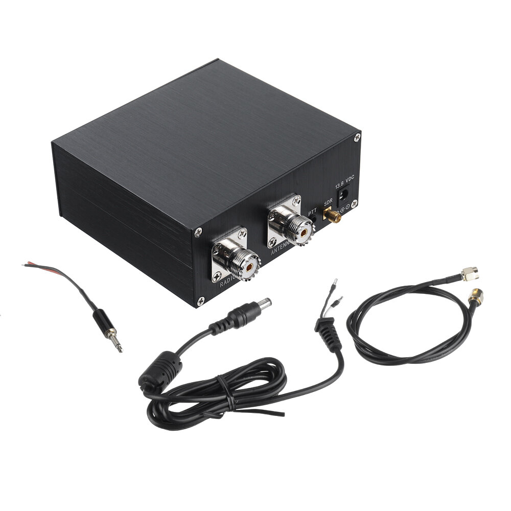
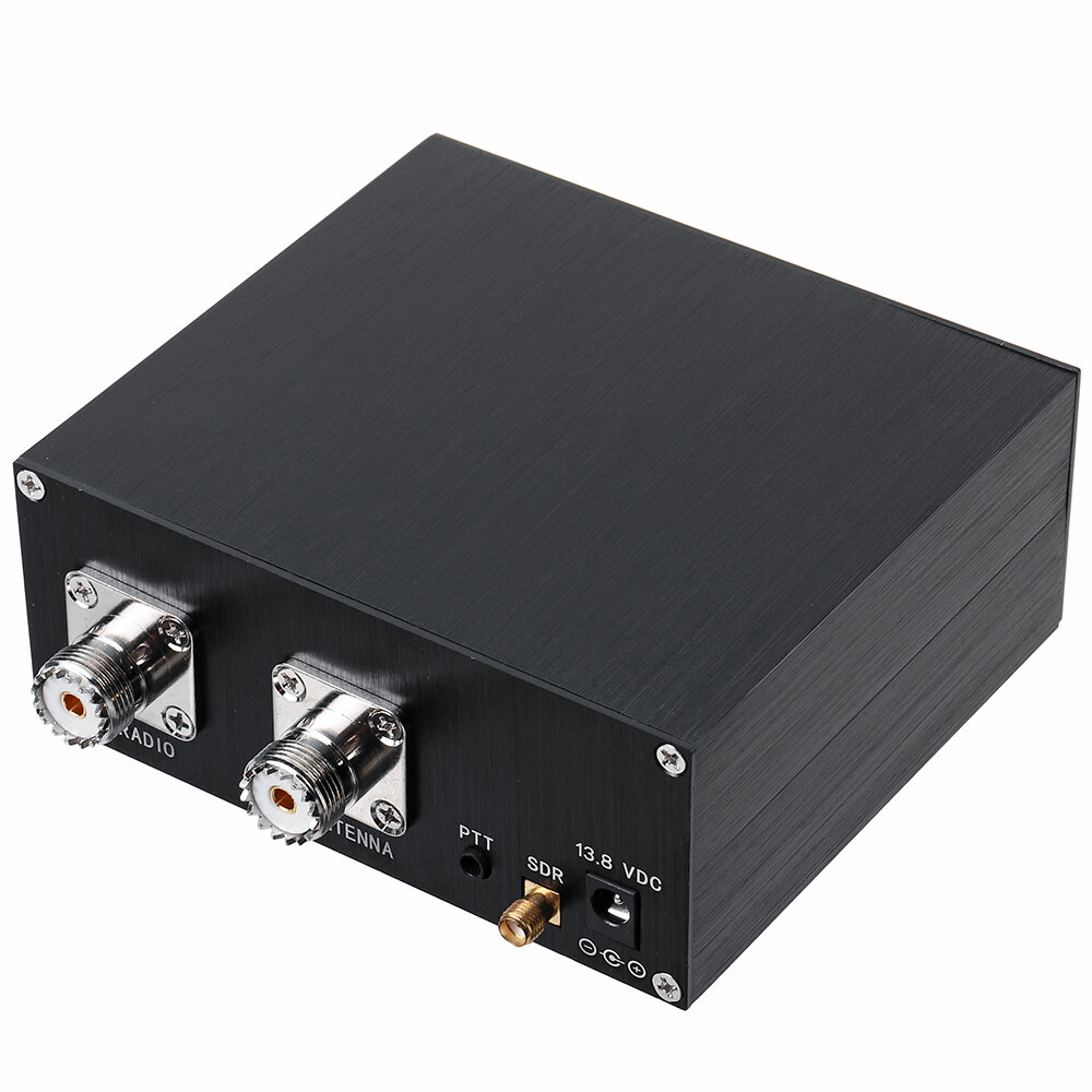
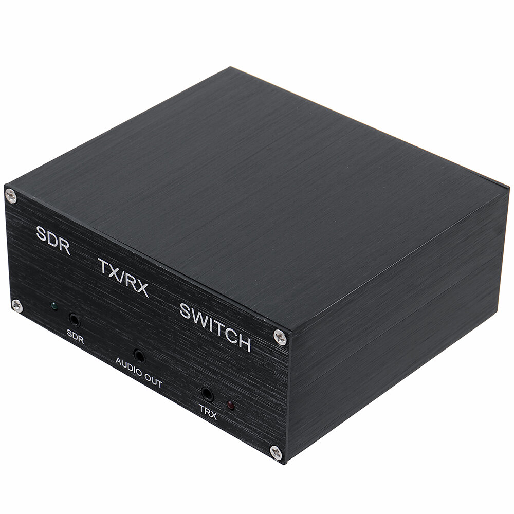
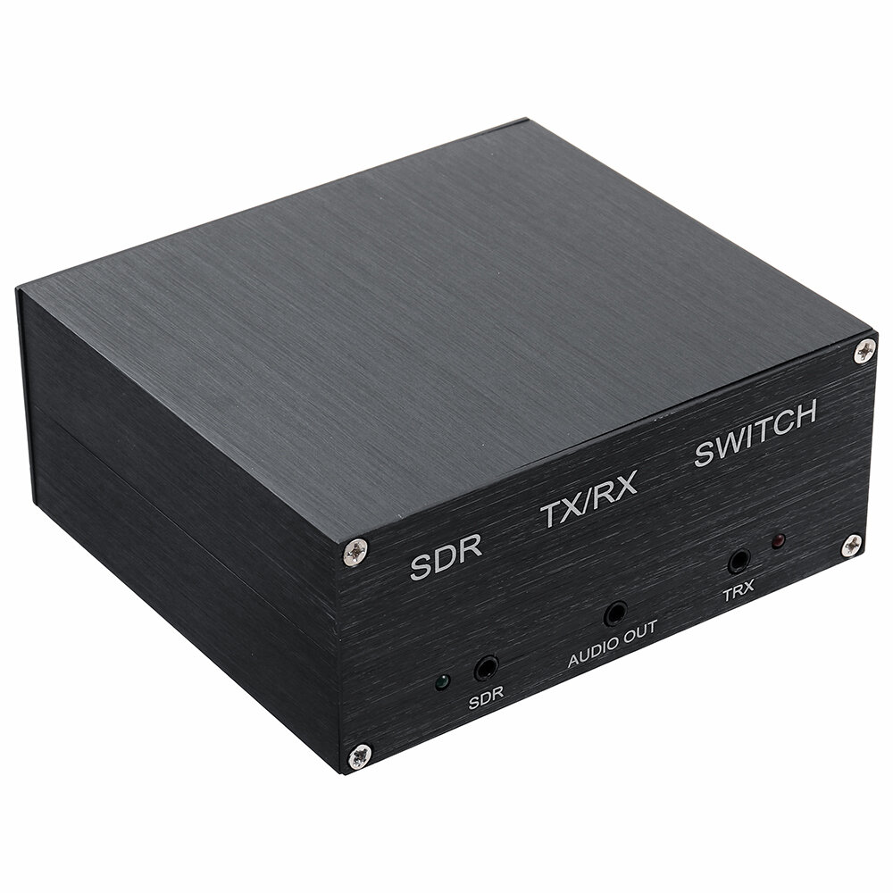
This is a very good panadapter switch so you can use your HF antenna (or upto 160Mhz) with your radio and your SDR receiver at the same time. This allows me to view a wide live bandscope on my computer using SDRUno and control the HF radio via Omnirig. To see this in action please search YouTube for Tech Minds.


arrived in about a week I moved the internal jumper to share the antenna. The device works perfectly. Sharing my DX Commander antenna with my Icom 706 transceiver and my SDRplay2. Now I have a waterfall display while using my old 706. Recommend this SDR Switch.


Tips:For questions about your order, place of delivery, product discount, taxation, delivery time, warranty, shipping, payment, exchange rate, and other questions unrelated to the product, please contact customer service.
A part of the QA has been auto-translated.
 0 Liked Saskira Gehituta
Jaso markaren berri eta %15 deskontua zure lehenengo eskaeran.
USD $ | United States USD $ | United States
GBP £ | United Kingdom
HKD HK$ | Hong Kong
CNY ¥ | China
JPY ¥ | Japan
EUR € | Euro
EUR € | Germany
EUR € | Italy
EUR € | Spain
SBD SI$ | Solomon Islands
PGK K | Papua New Guinea
THB ฿ | Thailand
ILS ₪ | Israel
VND ₫ | Vietnam
MGA Ar | Madagascar
XAG | Silver
IDR Rp | Indonesia
HTG G | Haiti
PHP ₱ | Philippines
MXN $ | Mexico
WST WS$ | Samoa
CAD $ | Canada
LSL L | Lesotho
BWP P | Botswana
KRW ₩ | South Korea
KWD د.ك | Kuwait
LAK ₭ | Laos
LKR Rs | Sri Lanka
TRY ₺ | Turkey
PKR Rs | Pakistan
CHF Fr | Switzerland
PLN zł | Poland
QAR ر.ق | Qatar
NAD N$ | Namibia
MOP MOP$ | Macau
EGP ج.م | Egypt
MWK MK | Malawi
VES Bs.S | Venezuela
ECS S/ | Ecuador
OMR ر.ع. | Oman
XDR | IMF
LTL Lt | Lithuania
TJS SM | Tajikistan
BBD Bds$ | Barbados
BRL R$ | Brazil
BZD BZ$ | Belize
CRC ₡ | Costa Rica
IRR ﷼ | Iran
AED د.إ | United Arab Emirates
PAB B/ | Panama
VUV VT | Vanuatu
DOP RD$ | Dominican Republic
XOF CFA | West Africa
AWG ƒ | Aruba
YER ﷼ | Yemen
XCD EC$ | East Caribbean
GHS GH₵ | Ghana
BDT ৳ | Bangladesh
SRD $ | Suriname
GMD D | Gambia
MVR Rf | Maldives
SVC $ | El Salvador
BND B$ | Brunei
GIP £ | Gibraltar
SHP £ | Saint Helena
GTQ Q | Guatemala
AFN ؋ | Afghanistan
IQD ع.د | Iraq
AZN ₼ | Azerbaijan
JOD د.ا | Jordan
CLP $ | Chile
BHD .د.ب | Bahrain
NIO C$ | Nicaragua
NGN ₦ | Nigeria
UZS so'm | Uzbekistan
ERN Nfk | Eritrea
ANG ƒ | Netherlands
KYD CI$ | Cayman Islands
SYP £S | Syria
SDG ج.س. | Sudan
LBP ل.ل | Lebanon
HNL L | Honduras
DJF Fdj | Djibouti
TTD TT$ | Trinidad and Tobago
KHR ៛ | Cambodia
AOA Kz | Angola
RWF FRw | Rwanda
GNF FG | Guinea
GEL ₾ | Georgia
FKP £ | Falkland Islands
BOB Bs. | Bolivia
CDF FC | Congo
ETB Br | Ethiopia
LRD L$ | Liberia
SOS Sh | Mali
DZD دج | Algeria
BIF FBu | Burundi
SAR ر.س | Saudi Arabia
UYU $U | Uruguay
UGX USh | Uganda
AMD ֏ | Armenia
MDL L | Moldova
SGD S$ | Singapore
LYD ل.د | Libya
MAD د.م. | Morocco
ZAR R | South Africa
TWD NT$ | Taiwan
HUF Ft | Hungary
XAF CFA | Central Africa
SEK kr | Sweden
RON lei | Romania
FJD FJ$ | Fiji
DKK kr | Denmark
CVE $ | Cape Verde
RSD din | Serbia
ISK kr | Iceland
MZN MT | Mozambique
ALL L | Albania
BGN лв | Bulgaria
BAM KM | Bosnia and Herzegovina
XPF F | Pacific
TND د.ت | Tunisia
JMD J$ | Jamaica
CNH ¥ | China
CZK Kč | Czech Republic
SZL E | Eswatini
AUD $ | Australia
NOK kr | Norway
KES KSh | Kenya
NZD $ | New Zealand
MNT ₮ | Mongolia
RUB ₽ | Russia
KZT ₸ | Kazakhstan
XAU | Gold
KGS с | Kyrgyzstan
INR ₹ | India
NPR रू | Nepal
TOP T$ | Tonga
ETH Ξ | Ethereum
SCR ₨ | Seychelles


